The other week, talk on the australian ham radio Facebook wall turned to kit radios and the Pixie QRP Kit. A number of options were shown and talked about, after a search and comparison, I chose to purchase this Versions of the kit from This eBay seller. with free postage it was around $8.
The kit arrived in about two week’s and a bit, and i had a chance to build it up last night. Construction was very simple, my kit came with many more comments than was needed, and i had populated the PCB pretty quickly.


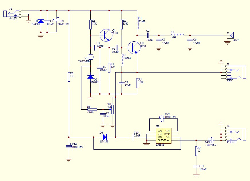
I started with the ceramic capacitors, the resistors, followed by the remaining components before finishing with the larger items.


Then came the nervous power up, I wasn’t really prepared, and didn’t really have the proper power options or connectors to listen via the headphone socket, or send the CW with the key. I always wonder if my really bad soldering skills would cut the mustard! No smoke emerged and I was on the air.


I initially started with a 9v battery I had temp soldered to the unit, but kept searching and found a DC lead with connector that fitted the unit. Their are only VERY limited specs on the device, the device PCB shows 9-12v screen printed on it. My radio power supply is 13.8v, my sota LiFePo4 13.2v nominal, i grabbed the sota battery and connected this up, the device worked, so I stayed on the external power.
Power supply: DC 9v - 12v
Antenna: 50 ohms, is not balanced,7MHZ band, standing wave ratio below 1.8
Receive the static current: 10ma @ 9 v
Transmission power: 0.8W @ 9 v, 1.2W @ 12 v
Frequency range: 7.023 MHz launch, receive 7.023-7.026 MHz (7.023 MHz crystals)
Stray (harmonic) inhibition: - 20 db
Working pattern: CW
I found enough connectors and bits and pieces that enabled me to hear the audio, and get the CW paddle to work (only one of the paddle arms worked, but that was enough). I got my Sota Elecraft T1 ATU and connect this to my dipole and I started to have a play. The device worked. I could hear some CW in the background, and I could send CW, (could hear the CW back on the main radio without antenna) I even had the Reverse Beacon network see me in VK3 and VK4.
The unit has a variable resistor on the PCB, this appears to adjust the frequency/tone slightly, I disconnected the external antenna, plugged in a 5w dummy load and I was playing with the resistor and listening back to the audio when. It Stopped!! No smoke, but the Output transistor, a s8050d331 was too hot to touch. I had a bit more of a look around and guessed id just cooked this, with too many volts in!. I desoldered it and put it on the component tester, and it complained, I’m sure this is all I’ve cooked. 5 mins later I ordered 10 replacements form an Australian eBay for a dollar posted. They should arrive in a couple of days, then to re-install and see if thats all Ive blown up!..
The kit was very easy to build, and worked straight away, only my *Ham Fistedness with the power caused the issue. When I get a moment, ill visit altrsonics and buy a small box and a 9v battery lead so I don’t repeater my “destruction”. Im also wondering if I could incorporate this simple touch CW paddle. And make it my ultra light travel radio! For $8, you can’t go wrong!.


I did the same with the same result. 9-12v … hunf. Since I bought three of them next week I’ll try again. Well, talking about bad soldering, one question: is it really necessary to the tin flow completely to the component side of the PCB? 73’s
Cool
Vk3ftom
What was the end result? Did replacing the transistor solve the problem or did that one burn up also? I am having the same issue except smoke comes out when I key (and RX doesn’t seem to be RXing).
TNX, W3KEV
it worked again, I just moved onto other projects..
Glad to hear it. I replaced the transistor and cleaned up a few of my sub-par solder joints yesterday and that worked. 73!